Preface
This research guide consists of two parts. The text part covers the background of the project, introduction and motif-find algorithm analysis. The video part covers the pre-processing method for fMRI of brain regions, ROI selection.
Background
In the study of human intelligence, researchers have long sought to understand the relationship between the functional organization of the brain and individual cognitive abilities. One approach to this problem is to use functional MRI to obtain the brain network in response to a particular stimulus, and then apply algorithms based on graph theory to analyze the structure and function of the network. In this project, two brain network modeling methods were implemented: regularized inverse covariance(Schmidt, 2006) and Conservative PC (CPC) (Ramsey et al, 2006). Three motif-searching methods were also used to analyze changes in network motif over time: FANMOD (Wernicke and Rasche, 2006), MAVisto (Schreiber and Schwöbbermeyer, 2005), and GK (Grochow et al, 2007). These algorithms were applied to data collected from participants performing twelve subtasks from an established intelligence test in order to uncover patterns and temporal information in the brain network. The fMRI dataset under 12 subtasks of this project is from Openneuro (https://openneuro.org/) based on the paper(Soreq et al, 2021). The process of the dataset uses SPM12(https://www.fil.ion.ucl.ac.uk/spm/software/spm12/), Marsbar (https://marsbar-toolbox.github.io/) and AFNI (https://afni.nimh.nih.gov/).
Why I Made This
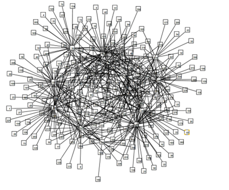
Fig1: Network generated from fMRI data by L1 precision algorithm
I am an undergraduate student majoring in Computer Science at the University of Michigan. I also have a minor in Complex Systems and Statistics. In the fall semester of 2022, I took the class CONMPLXSYS501 Introduction to complex systems. I was fascinated by many of the concepts in complex systems, especially the section on network analysis, especially for its application in neuroscience. Understanding how the human brain works may help us to explore the potential of artificial intelligence and to accomplish real artificial intelligence. Therefore, I chose the analysis of brain networks for my final project.
So, I decided to focus on the analysis of brain networks for my final project, but found the project to be more challenging than I had anticipated. In order to better understand the topic, I spent a considerable amount of time researching neuroscience concepts and learning about the processing of fMRI data and the pros and cons of different algorithms for network modeling. Despite facing limited personal computing resources and other challenges, I persevered and completed my project. This experience has given me a deeper appreciation for the rigors of scientific research and the thrill of exploring uncharted territory.
Introduction
A network motif is a small, recurring pattern that occurs within the structure of a network. These patterns are thought to play a key role in the functioning of the network by providing a basic building block for the organization and operation of the system. For example, in a biological network, a motif might represent a specific interaction between proteins that has a particular biological function. To do this in brain, researchers use functional magnetic resonance imaging (fMRI) data to construct brain networks, and then apply algorithms based on graph theory to search for network motifs. However, motif research on Brain Network focus more on Resting-State network or under single task.
Static data cannot help us understand the underlying logic of how the brain operates. To solve this problem, I modeled brain fMRI for subjects participating in each of the 12 intelligence tests, and perform motif finding algorithm to them. This can help to reveal underlying organizational principles in brain and to understand how these patterns may be related to cognitive processes and behavior.
Approach
The project pipeline consists of the following three parts.
- pre-processing of FMRI timing data and selection of region of interest (ROI)
- acquiring the voxel timing signal and obtaining the brain network by network modeling.
- finding the feature nodes in the network using the motif finding algorithm.
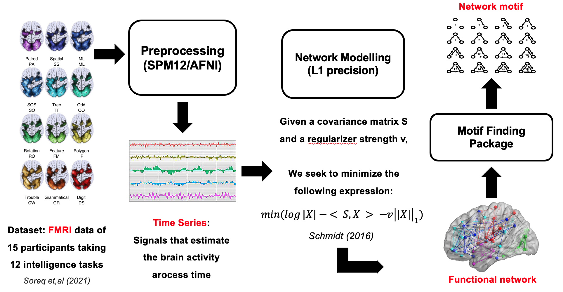
Fig2: pipeline of this project, containing pre-processing, network-modeling and motif-finding
Introduction to Basic Concepts
fMRI Pre-processing & ROI Selection
Network-modeling & Motif Finding
Network-modeling
In this study, the time-series data obtained from the previous step are fed into two algorithms, L1 precision(Schmidt, 2006) and Conservative PC (CPC)(Ramsey et al, 2006), to obtain undirected and directed graphs of brain network connectivity. L1 precision is a method that minimizes the log determinant of the matrix of connectivity weights while constraining the matrix to match the covariance of the input time-series data. This regularization helps to reduce the influence of noise in the data when the number of time points is limited (Smith et al, 2011). CPC is a variant of the PC algorithm that infers causal relationships between the time-series data. It uses a set of rules to determine the orientation of the edges in the network, with the goal of limiting the number of false orientations(Ramsey et al, 2006; Smith et al, 2010). Since L1 precision is effective at identifying direct relationships between the time-series data, while CPC is particularly good at inferring causal relationships. By applying both methods, this study aims to uncover the different topological properties of functional connectivity in the brain.
Motif-finding
Network motif-finding algorithms are a class of computational methods used to identify recurrent patterns of connections within a network. These algorithms can be distinguished into two broad categories: frequency-based and significance-based. Frequency-based algorithms determine the number of occurrences of each motif within a network and report the most frequent motifs. In contrast, significance-based algorithms evaluate whether the observed number of occurrences of each motif is statistically significant compared to a null model of the network. In this study, three motif search algorithms or packages are used to identify network motifs in the brain connectivity data: FANMOD, MAVisto, and Grochow-Kellis.
- FANMOD (Wernicke and Rasche, 2006) is an efficient algorithm that uses unbiased nodes to sample the network and ensures that each subgraph is only searched once, without generating redundant or meaningless subgraphs. It employs a new analysis method called DIRECT to assess the significance of identified subgraphs, rather than using random networks as null models.
- MAVisto (Wernicke and Rasche, 2006), on the other hand, uses a pattern tree and the downward closure property to build subnodes by adding edges one by one according to the root nodes. It then evaluates whether the current subgraph is below a predefined threshold and, if so, discards any remaining new or reversed edges until there are none left.
- The Grochow-Kellis (Grochow et al, 2007) algorithm aims to find all possible mappings of a given query graph in the network, which it does by first calculating the symmetric breaking condition of the query graph and then using the branch and bound method to search for all possible mappings that meet this condition. These three algorithms represent different classes of motif search methods and can be used to evaluate and compare the results of motif searches in the brain connectivity data.
Conclusion
In this study, a total of 15 subjects are selected to undergo motif analysis. For each subject, 12 undirected graphs are inferred from L1 precision and 12 directed graphs are inferred from Conservative PC (CPC) for each of the 12 tasks. Then, for each graph, motif searching is performed using the three algorithms described above to identify motifs with 3, 4, and 5 nodes. The results from all 15 subjects are averaged for each task to obtain the motif distribution for 3, 4, and 5 nodes from both the undirected and directed graphs. This allows for the comparison of the unique motif search results for each task.
After combining the results from the FANMOD, MAVisto, and Grochow-Kellis algorithms, it was found that the dominant motifs identified by these methods are similar. Therefore, the results from FANMOD were used for further analysis.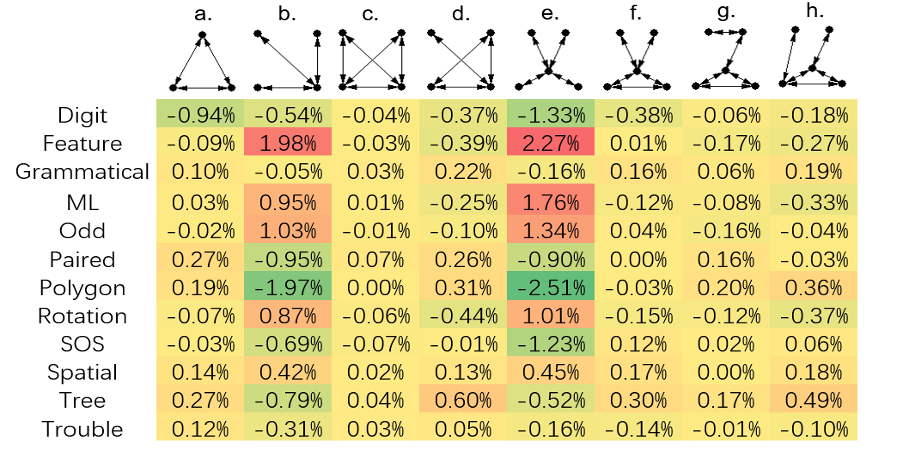
Fig3: The representative motif found in undirected network with 3, 4 or 5 nodes
In the results obtained from the undirected network, only motifs with a p-value <= 0.05 and a frequency >= 0.5% were selected for further analysis. Figure 3 shows the distribution of these motifs for each task, with each row representing a different task and each column representing a different motif. The values in the table are the average frequency of each motif across all tasks, with each value being subtracted from the average to show how far a given motif is from the average value across all tasks.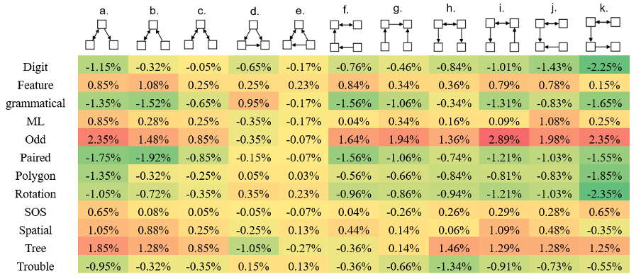
Fig4: The representative motif found in directed network with 3, 4 or 5 nodes
The directed network in Figure 4 exhibits a similar pattern to the undirected network in Figure 3, where different tasks have a distinctive distribution of motifs compared to Figure 3. Motifs that are more responsive to changes in tasks tend to have a high correlation with each other. For example, as shown in Figure 5, Figure 4a and Figure 4j show a correlation value of 0.97, indicating that certain motifs can perform similar functions, even if they are not subnetworks of each other (such as Figure 4a and Figure 4b). Additionally, Figure 4c, Figure 4d, and Figure 4e match motifs found in existing research on brain networks, but show little change among different tasks, possibly indicating that these motifs serve more general functions than others.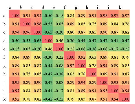
Fig5: The pairwise correlation among a-k
The analysis of the 5-node motifs in the directed network yielded noteworthy results, as several motifs were found to be statistically significant across the 12 tasks studied. However, it was observed that the frequency of the motif AT8NOLYF was disproportionately high in the Digit, Paired, and Polygon tasks, in comparison to both other motifs within these tasks and across other tasks. This suggests that the motif AT8NOLYF may perform a common function among these tasks, as outlined in Alon’s (2007) review of similar motifs.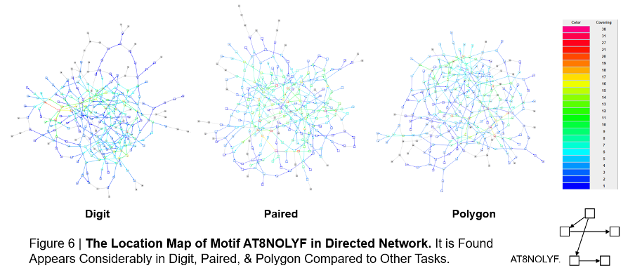
Reference
- Alon, U. (2007). Network motifs: theory and experimental approaches. Nature Reviews Genetics, 8(6), 450-461.
- Grochow, J. A., & Kellis, M. (2007, April). Network motif discovery using subgraph enumeration and symmetry-breaking. In Annual International Conference on Research in Computational Molecular Biology (pp. 92-106). Springer, Berlin, Heidelberg.
- Ramsey, J. Zhang, J. Spirtes, P. (2006). Adjacency-faithfulness and conservative causal inference. Proceedings of the 22nd Annual Conference on Uncertainty in Artificial Intelligence.
- Schmidt, M. (2006) L1precision: Matlab code for MAP estimation of Gaussian Graphical Model Precision with L1-regularizer. Retrieved from http://www.cs.ubc.ca/~schmidtm/Software/L1precision.html.
- Schreiber, F., & Schwöbbermeyer, H. (2005). MAVisto: a tool for the exploration of network motifs. Bioinformatics, 21(17), 3572-3574.
- Soreq, E., Violante, I. R., Daws, R. E., & Hampshire, A. (2021). Neuroimaging evidence for a network sampling theory of individual differences in human intelligence test performance. Nature communications, 12(1), 1-13.
- Wernicke, S., & Rasche, F. (2006). FANMOD: a tool for fast network motif detection. Bioinformatics, 22(9), 1152-1153.
Appendix
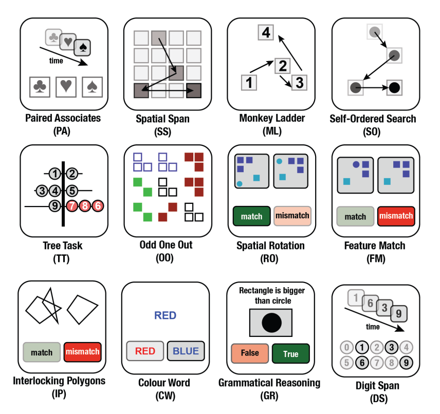
a. Task description
Note: the below information is from supplementary materials of Soreq et al (2021).
- Paired (PA): This task is based on a paradigm commonly used to assess memory impairments in ageing clinical populations.
- Spatial (SS): Based on the Corsi Block Tapping Task, which is a classical task for measuring spatial short-term memory capacity.
- ML (ML): Visuospatial working memory task based on the non-human primate literature.
- SOS (SO): Based on a test used to measure strategy during search behaviour.
- Tree (TT): Spatial planning task based on the Tower of London Task, which is widely used to measure executive function.
- Odd (OO): A deductive reasoning task based on a sub-set of problems from the Cattell Culture Fair Intelligence Test.
- Rotation (RO): Tasks of this type are typically used to measure the ability to manipulate objects in mind.
- Feature (FM): Based on classic feature search tasks that have been historically used to measure attentional processing.
- Polygon (IP): Based on the Interlocking Pentagons task, which is often used in the assessment of age-related disorders.
- Trouble (CW): (Colour Word) - This is a more challenging variant on the Stroop test.
- Grammatical (GR): This is a verbal reasoning task based on Alan Baddeley’s 3-minute grammatical reasoning test.
- Digit (DS): Is a computerised variant on the verbal working memory component of the WAIS-R intelligence test.